

The basic structure of pure sine wave inverter
The core of the inverter device is the inverter switch circuit, referred to as the inverter circuit for short.
The direct function of a pure sine wave inverter is to convert DC power into AC power
The core of the inverter device is the inverter switch circuit, referred to as the inverter circuit for short.
This circuit completes the function of inverter by turning on and off the power electronic switch. The on-off of power electronic switching devices requires certain driving pulses, and these pulses may be adjusted by changing a voltage signal. Circuit that generates and regulates pulses. Usually called control circuit or control loop. The basic structure of the inverter device, in addition to the above-mentioned inverter circuit and control circuit, there are protection circuits, output circuits, input circuits, output circuits, etc., as shown in Figure 1.
The working principle of the inverter: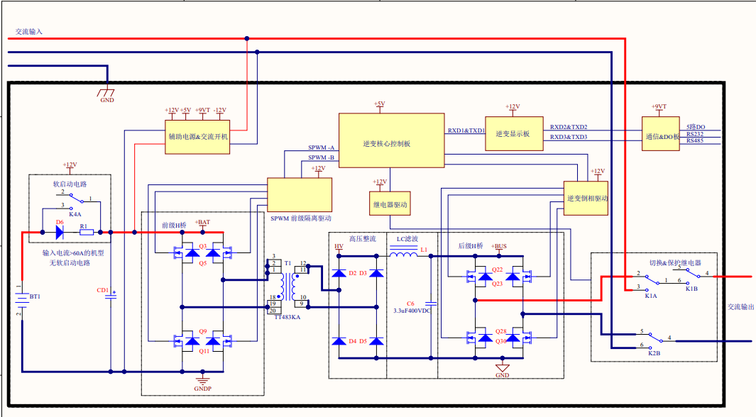
The commonly used single-phase output full-bridge inverter main circuit, and PWM pulse width modulation controls the on or off of the IGBT tube. In the circuit, the inductance L can limit the discharge current of the commutation capacitor C, extend the discharge time, and ensure The turn-off time of the circuit is longer than the turn-off time of the thyristor, and a large-capacity capacitor is not needed. D1 and D2 are two feedback diodes, which can release the energy in the inductance L and send the remaining energy in the commutation back to the power supply to complete the energy feedback function.
The above is the information provided by bwitt, I hope it will be helpful to you!